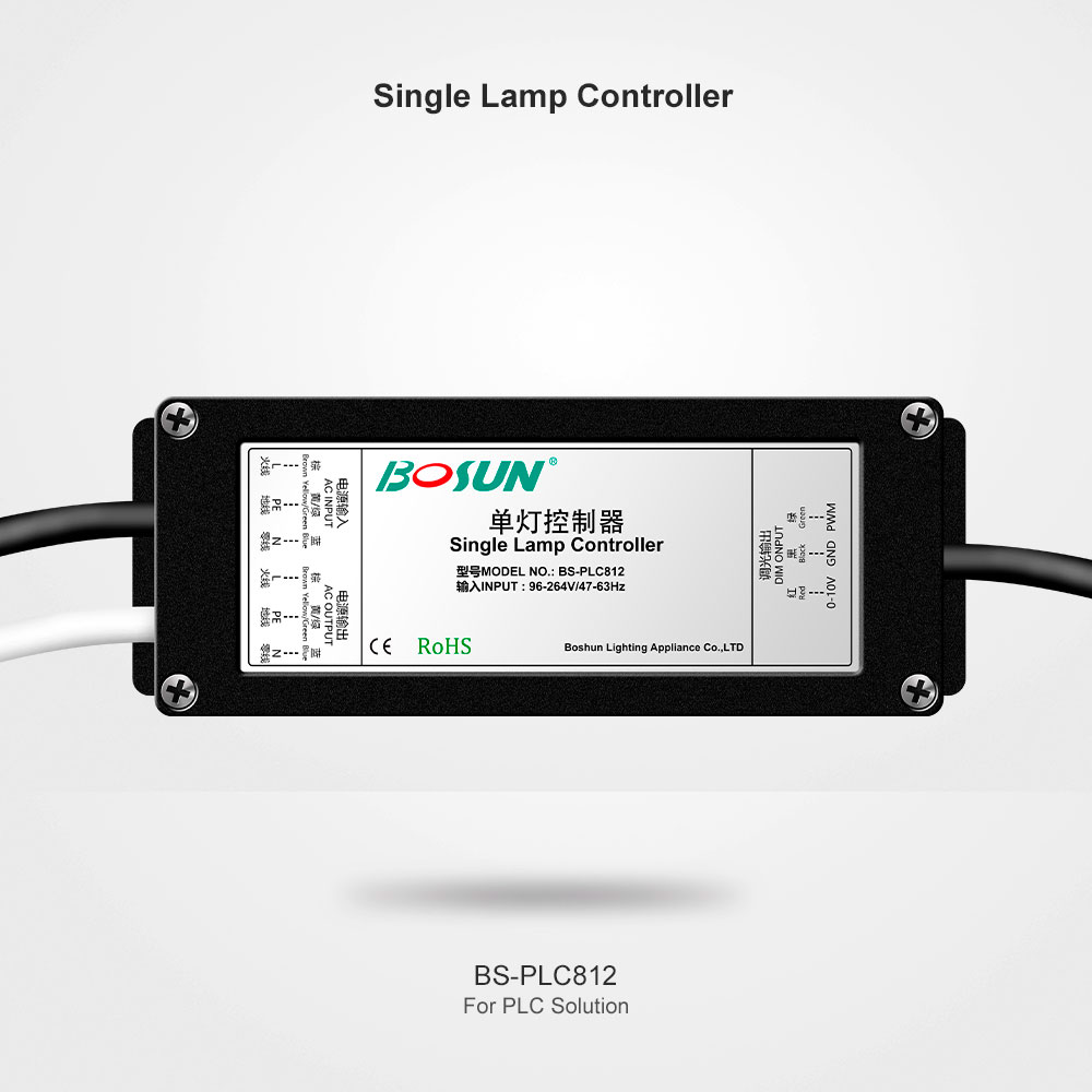
Gebosun® Single Lamp Controller BS-PL812 for PLC Solution

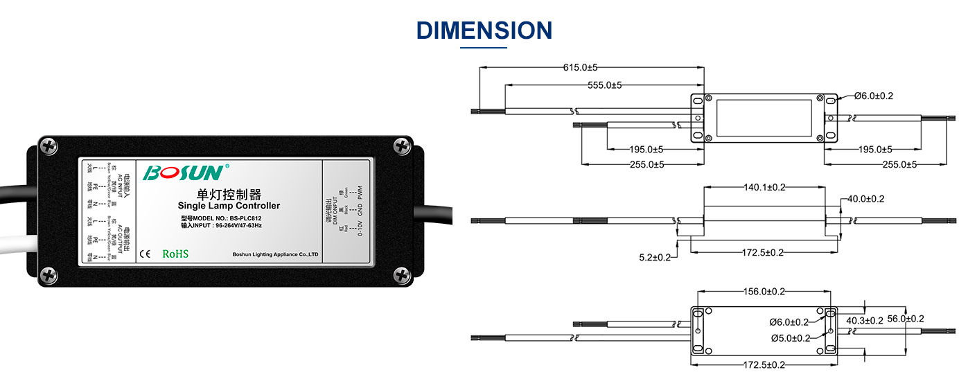
Dimension
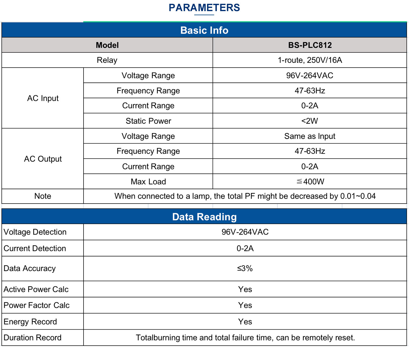
·Remotely turn ON/OFF, built-in 16A relay;
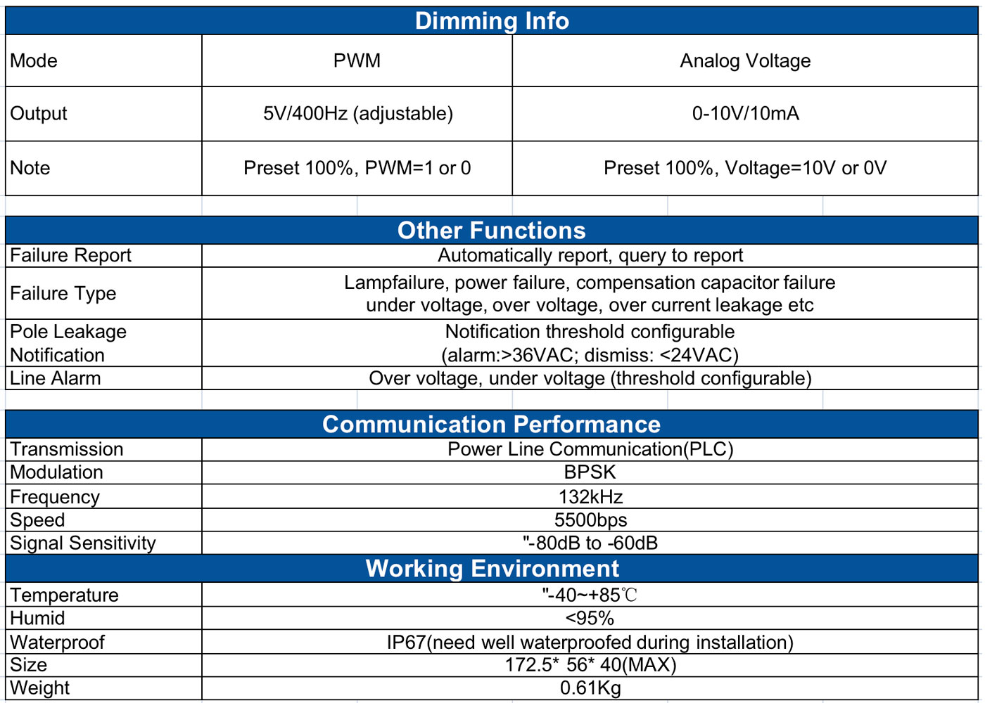
·Support dimming interface: PWM and 0-10V:
·Failure detection: lamp failure, power failure, compensation capacitorfailure, over voltage, over current, under voltage, leakage voltage;
·Lamp failure detection: LED lamp and traditional gas discharge
(including compensation capacitor failure);
·Automatically report failure notification to server and all trigger thresholds are configurable;
·Built-in power meter, support remotely read real-time status and parameters like voltage, current, power and energy etc;
·Support recording total burning time and resetting.
·Support recording total failure time and resetting.
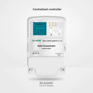
·Auto recognize its father node (concentrator):
·Leakage detection;
·Optional configuration: RTC and tilt
·Lightning protection;
·Waterproof: IP67:
·Thickness is only 40mm, more suitable for LEP lamps;

Please read this specification carefully before use, so as to avoid anyinstallation error that might cause the malfunction of the device.
Transportation and storage conditions
(1) Storage Temperature:-40°C~+85°C;
(2) Storage Environment:avoid any humid, wet env;
(3) Transport: avoid falling;
(4) Stockpiling: avoid over-piling;
Notice
(1) On-site installation should bebyprofessional personnel;
(2) Do not install the device in a long-termhigh temperature environment, which mightshorten its lifetime.
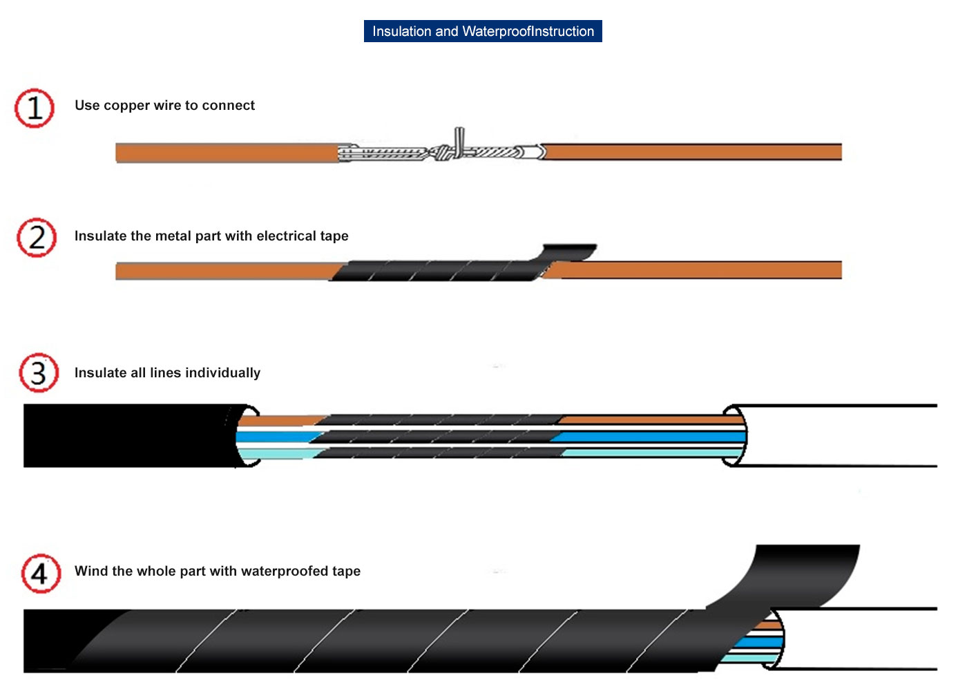
(3) Well insulate the connects during theinstallation;
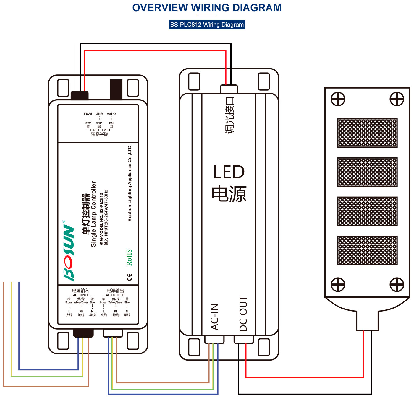
(4) Wire the device STRICTLY according tothe attached diagram, inappropriate wiringmight cause deadly damage to the device;
(5) Add a 6A fuse to the front of the lampcontroller AC input during installation;
(6) The antenna must be installed outsidethe shell. DO NOT put it inside.
(7) Make sure all the connection parts arewell waterproofed (see the instruction diagram in the end).
Description
AC input: 3*1.0 mm2, black jacket, brown(live), yellow green(ground), blue(null):
AC output: 3*1.0 mm2, white jacket, brown(live), yellow green(ground), blue(null);
Dimming output: 3*0.75mm2, black jacket, red(0-10V/DALl), green(PWM), black(GND).