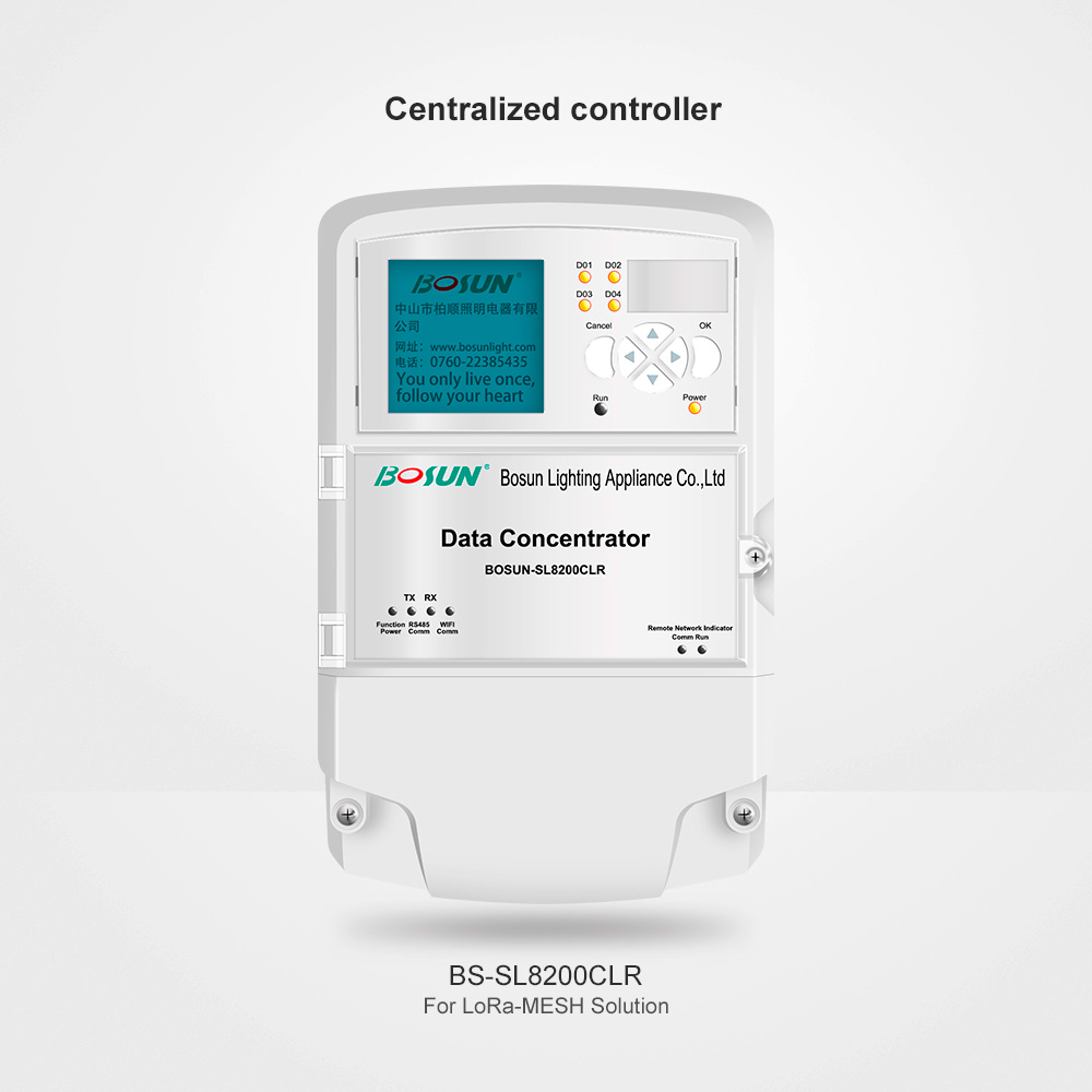
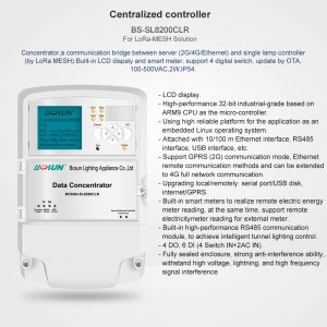
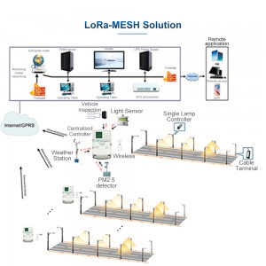
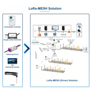
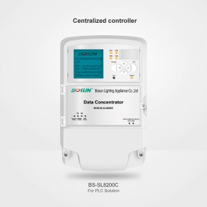
Gebosun® Centralized Concentrator BS-SL8200C for ZigBee Solution
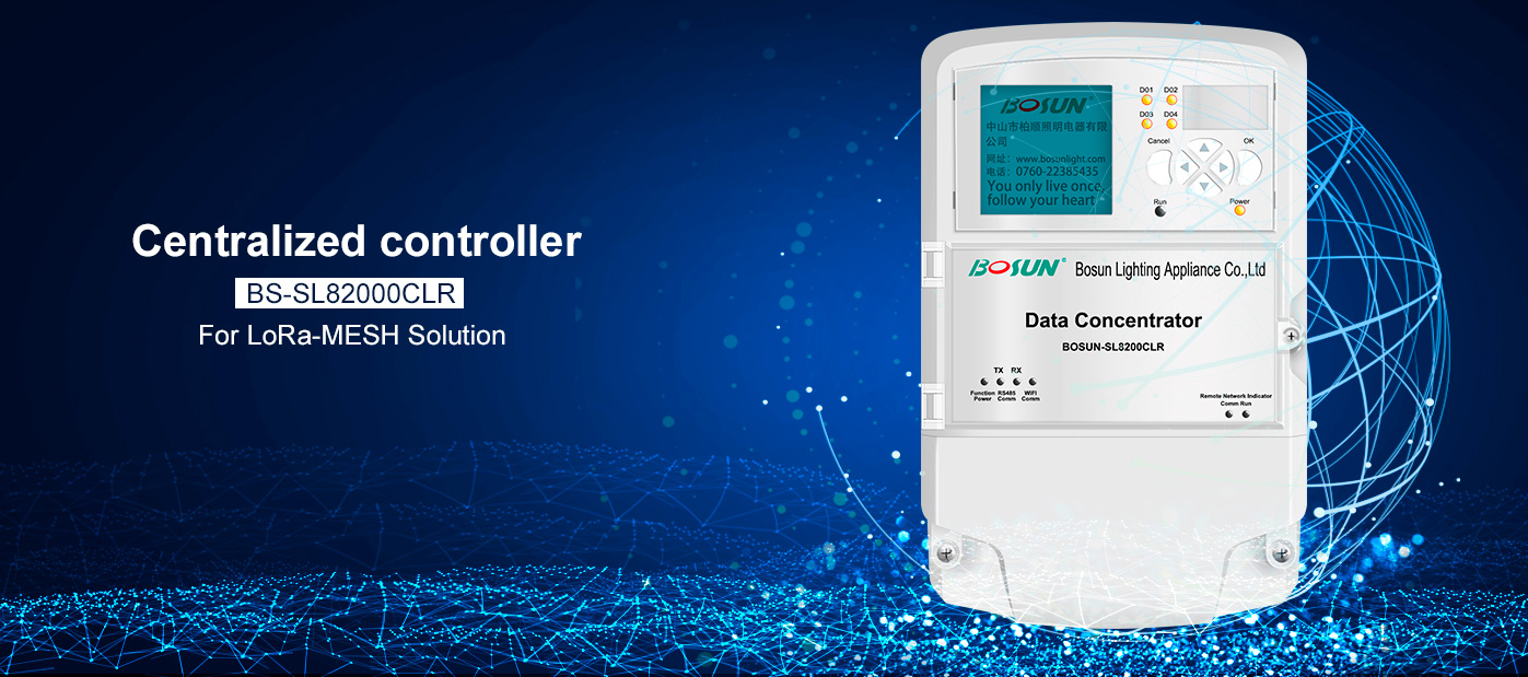
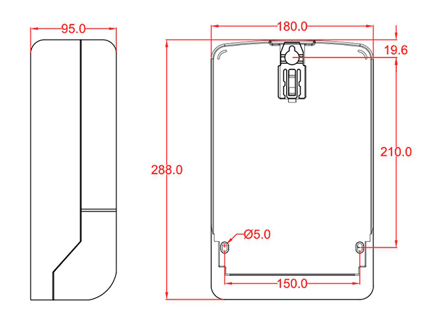
Dimension
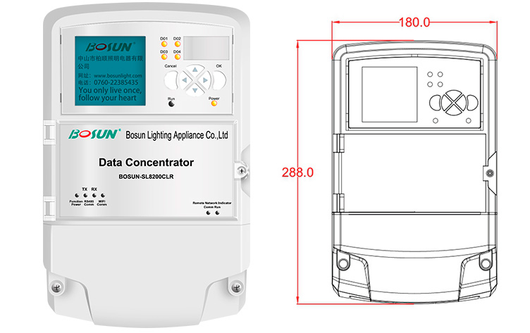
·LCD display
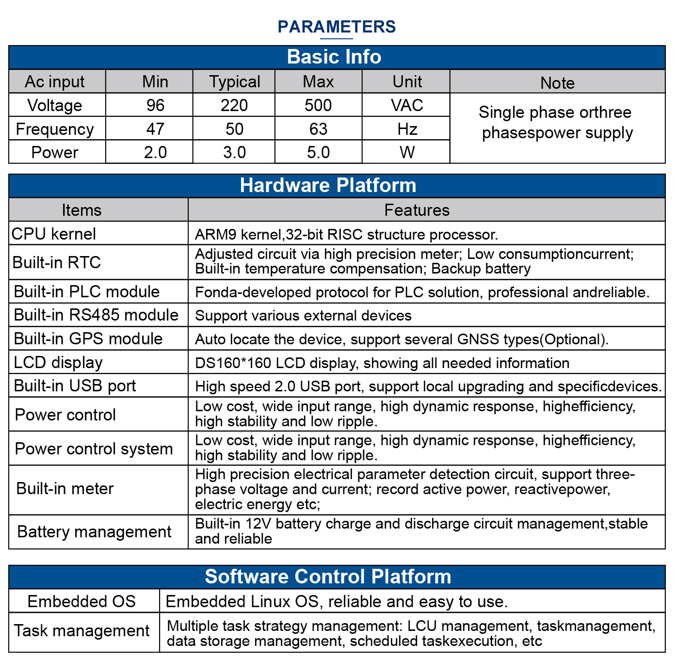
·High-performance 32-bit ARM9 MCU:
·Embedded Linux OS platform;
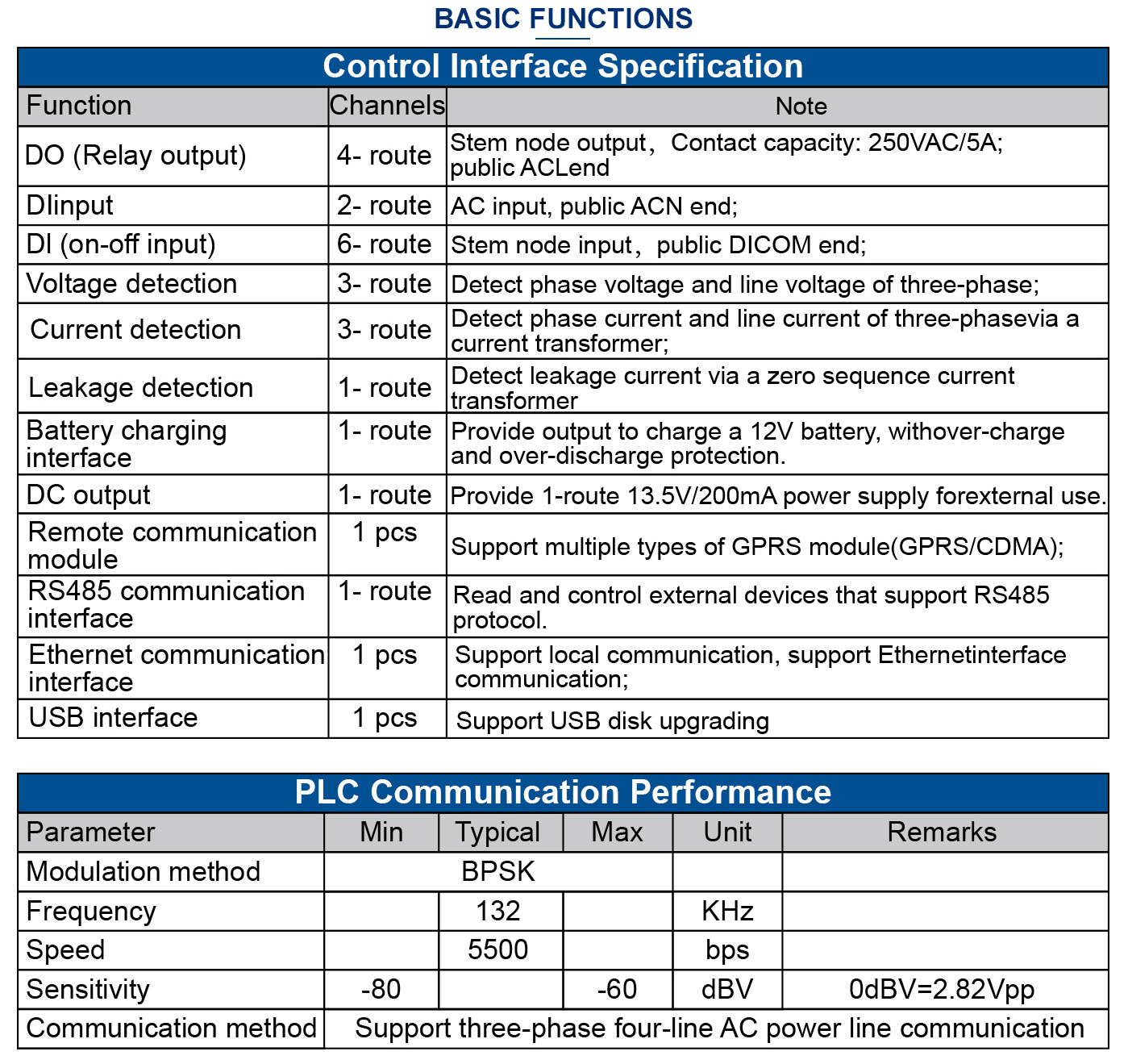
·With 10/100M Ethernet interface RS485 interface, USB interface;
·Support GPRS/4G and Ethernet communication mode;
·Firmware upgrading: online, cable and local USB disk;
·Built-in smart meter: remotely data reading
(including external meter);
·Built-in PLC communication module;
·Built-in 4 DO、8 DI(6DCIN+2AC IN);
·Built-in RTC, support local scheduled task;
·Optional configuration: GPS;
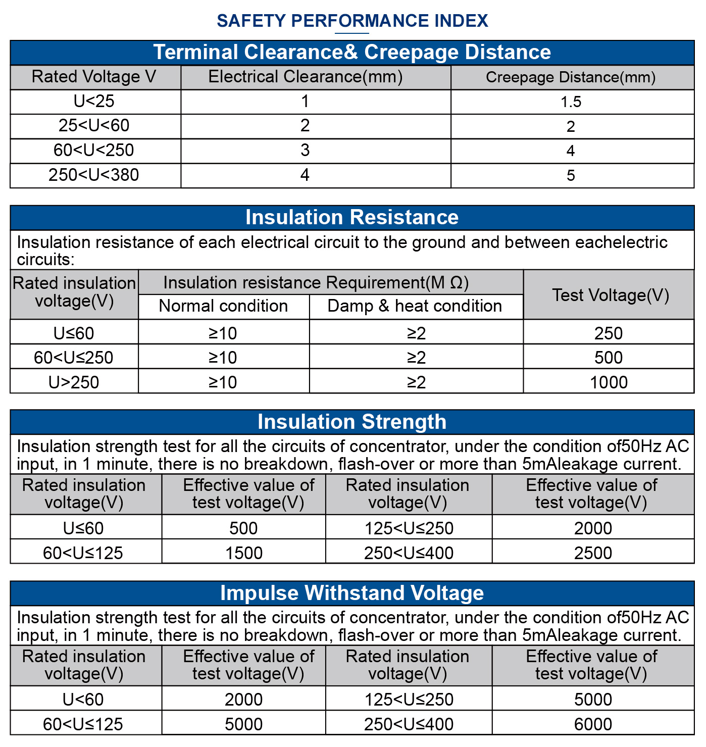
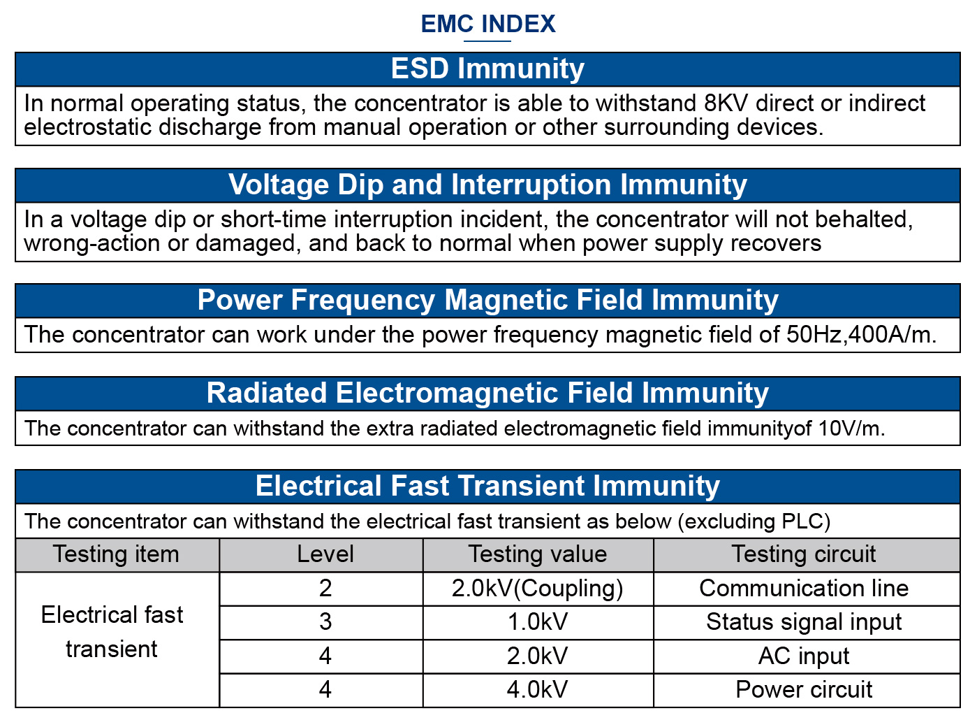
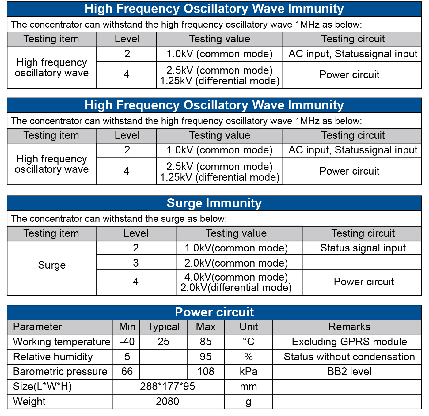
·Fully sealed enclosure: anti-interference, withstand high voltage,
lightning andhigh frequency signal interference;
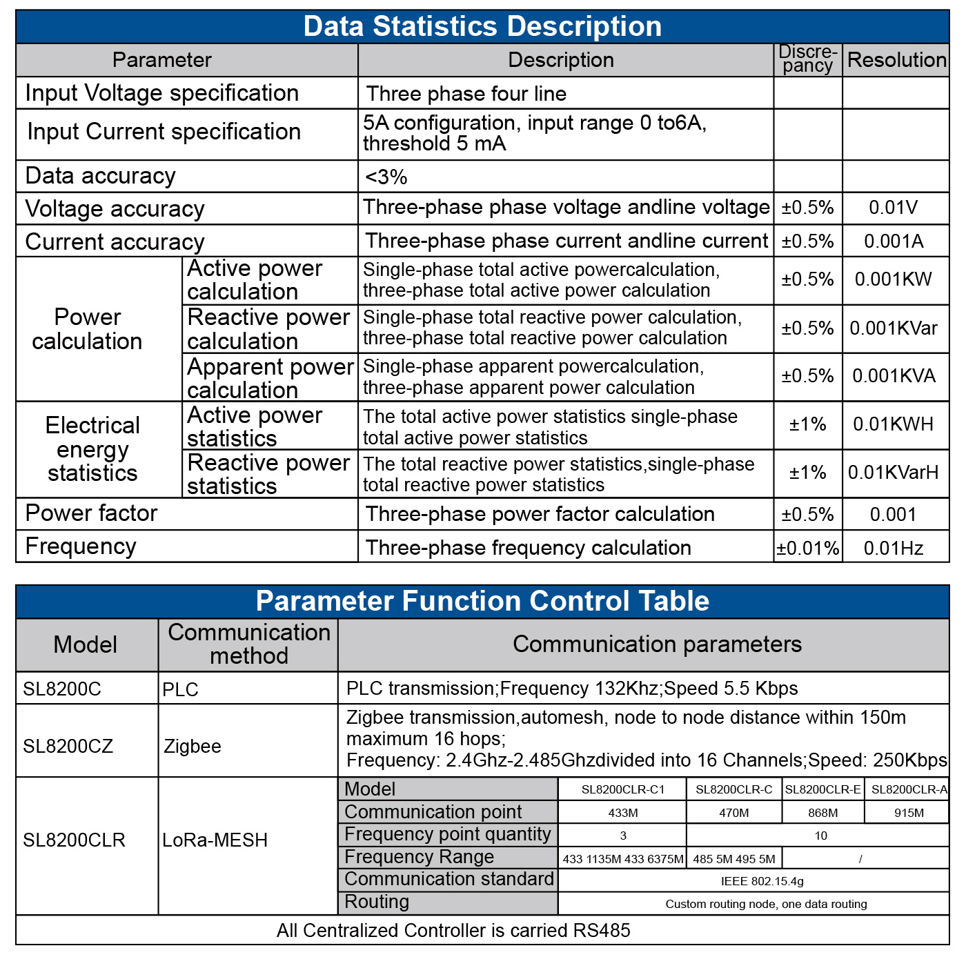
·Communication module replaceable:
BOSUN-SL8200C with PLC
BOSUN-SL8200CZ with ZigBee
BOSUN-SL8200CT with RS485
BOSUN-SL8200CLR with LoRa-MESH

Please read this specification carefully before use, so as to avoid
anyinstallation error that might cause the malfunction of
the device.
Transportation and storage conditions
(1) Storage Temperature:-40°C~+85°C;
(2) Storage Environment:avoid any humid, wet env;
(3) Transport: avoid falling;
(4) Stockpiling: avoid over-piling;
Notice
(1) On-site installation should bebyprofessional personnel;
(2) Do not install the device in a long-termhigh temperature
environment, which mightshorten its lifetime.
(3) Well insulate the connects during theinstallation;
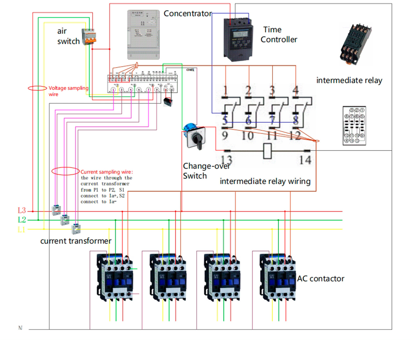
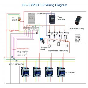
(4) Wire the device STRICTLY according tothe attached diagram,
inappropriate wiringmight cause deadly damage to the device;
(5) Add a 3P air switch to the front of the ACinput in order to ensure
safety:
(6) Install the antenna(if have) out of thecabinet for better wireless
signal.
Notice:
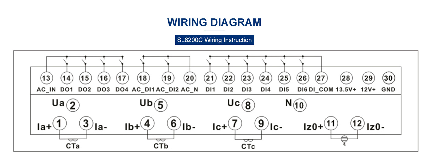
Ua, Ub, Uc are for AC input, N for null line;
la, lb, lc are for the current detecting input, they cannot be directly connected toAC ,and must install an AC transformer;
la, Ib, Ic must be STRICTLY connected to phase A/B/C ac input;
DO1-DO4 is for digital output to control the AC contactor;
A converter is needed to control 380V AC contactor, the common port is AC-IN, connecting to AC live line
lz is for leakage detection, need to connect to an external zero sequence current transformer to detect leakage current.
DI1-Dl6 is for digital input, the common port is DI COM, it cannot be connected to AC/DC current or voltage.
AC DI1,AC DI2 are for AC detection input, the common port is AC N, it cannot be connected to DC current or voltage.
12V+,GND are for external battery, positive and negative points must not be correct;
13.5V+,GND is for external power supply connection, providing DC 13.5V/200mA.
Please connect “+” “-” correctly, and make sure the external device current is no more than 200mA.
